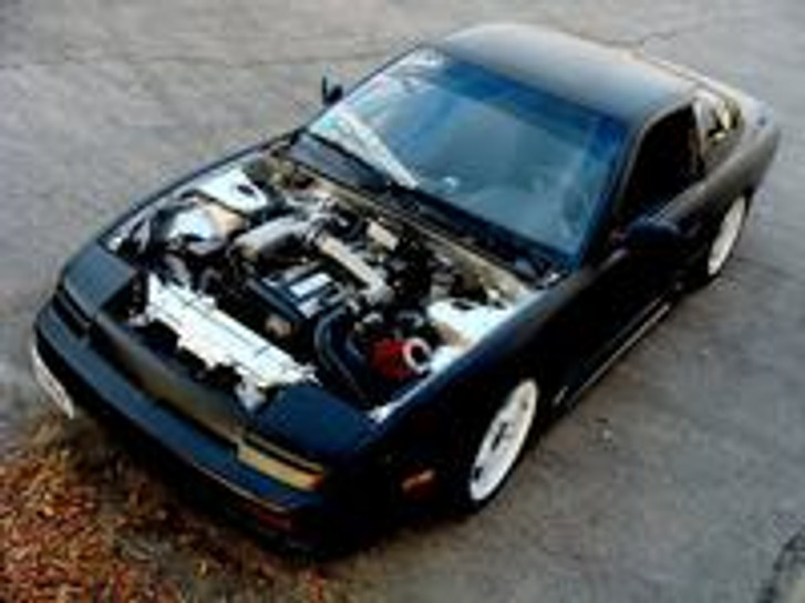
Well this is a simple little guide that I (Carl H) have decided to put together after completing my rb20 swap into my 240sx. The wiring pertains to a DOHC car but it seems in practice that SOHC and DOHC swaps are the same or near the same. Most of this information was derived from Brandon Baune’s rough wring guide, some things I added or subtracted to fit my needs. As with anything of this sort no warranty is provided and if you mess up your own car then its your problem not mine. Make sure you know what you are doing and if you don’t, then make it a point to find some one who knows what they are doing. Also don’t copy this document without giving props to me, plagiarism is bad, and I won’t be happy if someone comes out and starts to claim that this write up was their idea. Anyways enough of that lets get down to the real meat of the topic.
Ok. So you want to wire the car up eh? I hope that you have all the wiring harnesses from the clip, if you got a motor set then you might be in for a few trips to radio shack. First off you will need a few things before you wire the car.
Tools:
1. Soldering iron and solder
2. Electrical tape
3. Plumbing emergency tape (You can get this at the hardware store in the plumbing isle, this stuff is great for wrapping up your finished harnesses and is similar to the stock wire wrap, wont make the wires sticky like electrical tape will.)
4. Wire tap-ins (Get these from radio shack, they sell blue ones and red ones, if you want to do the wiring without soldering you will need a package of blue ones, but either way you will need a package of red ones)
5. Razor blade
6. Pliers
7. Wire strippers
Materials:
1. RB20DET harness
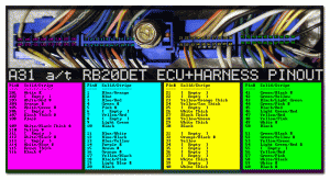
2. ECU pinout image (print this in color, or have it handy):
Procedure:
Locate the 6 and 8 wire connectors on the engine bay harness; they are big, gray, and quite square. Clip these back from the harness as far back as you can preferably about 20 inches, you will have to unsheathe/unwrap the harness to do so.
On the KA EFI harness locate the oval gray and brown plug, these were located near the fuse box in the 240, clip these back from the harness about 6in. or so. On my swap I only needed to use the gray oval plug but on the SOHC swap you might need to use both. It just depends, I know that the fuel pump wire is on the brown plug on my car but why use a plug when only one wire is being used?
Well by this point you should have located the major plugs of interest and should have them in your hand, so on to the next step.
Lets start the actual wiring by denoting which wire goes to which wire on what harness. I’m going to list the wire colours in columns with the RB wires being on the right and the ka wires being on the left.
KA - RB
Black/Red - Black/Red (Thick wire)
Red - White/Black (Thick wire)
Black/Pink - Black/Pink (Thin wire)
Black/Yellow - Black/White (Thick wire)
White/Red - White/Red (Thin wire)
FB White - White/Purple (Thick wire)
Alt. White/Blue - Terminal (V.Thick wire)
Ok, so we have the basic wire colours and what they connect to but where are the wires you say? Well have no fear as I have the locations of the wires and where they go along with pics for clarity.
The KA black/red wire connects to the RB black/red wire coming off the 6-wire RB connector this wire is on the gray oval ka plug. The KA red wire connects to the RB white/black wire also coming off of the 6-wire RB plug, this wire is also on the 6-wire RB plug.
The KA black/yellow wire is actually on a plug on the side of the fuse box, you can clip the plug off of your old ka and connect it to this for a clean connection or clip it off like I did, please note that the white wire is just cut, it is NOT spliced into the black/yellow wire and the black/white wire. The black/white wire is on the 8-wire RB plug.
Here is the write up for the lower harness
I thought it would be a good idea that while I had my motor on the ground I would do a write up of what needs to be done to the KA lower harness to make it fit onto the RB.
Series II RB25DET S13, all S13s should be the same. Do this at your own risk!!! I will not be responsible for your mistakes and this is based on my knowledge and experience with my RB.
WARNING: do this at your own risk!! I am not responsible for *Jack* blah blah, you know how it goes. Now this guide is only for those that know basic engine wiring, have some clue so far on what is going one but just need to know the specifics to get it started. Thanks OpenSource…
Also included I will should you how to properly splice wires. Don’t use gay splice/butt connectors they will only cause you pain in the long run and I will flame you. Spend the time and a little bit for materials and I promise all will go well and you will be glad you listened to me!
Now on with the show.
Prepping that Lower KA harness for your RB
1) Take off both harnesses from the KA and your RB motor
2) From your RB Harness cut off the Oil Pressure sending unit plug, it has two wires – YLW/WHT and B and it is located right next to the oil filter.
3) Now you are going to want to cut at least this much off because it has to be slightly extended.
The Yellow with white wire is for the oil light and the blue wire is for the oil gauge. The stock KA cluster doesn’t have an oil gauge so the blue wire won’t be used. If you are using the RB gauge cluster than you want to be using this blue wire and are going to have to hard wire it to the cluster. If you are using the stock cluster than cut the blue wire, or leave a pig tail on it if you plan to use a oil pressure gauge because that’s what its going to be hooked up to.
And lastly the write up for RB-s13 cluster.
Suits r32 type-m gts-t only.
Wiring colours for the ka cluster and rb cluster are from ‘93 cars may not be the same for earlier years.
RB
Plug 1
Gnd – black with yellow stripe (ground)
Tm – blue with black stripe (temperature gauge)
Oil – yellow with white stripe (oil light)
Belt – yellow with black stripe (seat belt light/chime?)
Door – red with white stripe (door open light)
Exh – orange with black stripe (exhaust gas sensor light)
Ign – green (ignition switch power)
Acc – blue (clock power)
Bat – yellow (no idea)
Plug 2
Ill+ – red with blue stripe (illumination power)
Ill – black (illumination ground)
Om – yellow with blue stripe (oil pressure gauge)
Tam – yellow with red stripe (tach signal)
Beam – black (high beam ground)
Beam+ – red with green stripe (high beam light power)
Gnd – black (ground)
Sw1 – yellow with green stripe (no idea)
Sw2 – black with yellow stripe (no idea possible ground)
Hicas – green with white stripe (hicas warning light)
Brk – white with purple stripe (handbrake/brake fluid warning light)
Chg – white with red stripe (alternator charging light)
Plug 3
Ign – green stripe (ignition switch power)
Bm+ – white with blue stripe(boost gauge signal)
Bm – black with yellow stripe (boost gauge ground)
Fm – green with blue stripe (gas gauge)
Gnd – black with yellow stripe (ground)
Fuel – red with black stripe (fuel warning light)
T/l – white with green stripe (left turn light)
T/r – green with yellow stripe (turn right light)
KA
Plug 1
Chk engine – red (check engine light)
Cruise – black (cruise control ground)
Cruise+ – green with white stripe (cruise control light power)
Abs – blue with red stripe (abs light)
Exh – red with blue stripe (no idea, different on every car)
Fm – green with blue stripe (fuel gauge)
Fuel – red with black stripe (fuel light)
Ill – red with yellow stripe (no idea)
2p – yellow with green stripe (no idea)
Japanese symbols – yellow with blue stripe (no idea)
Plug 2
Ill+ – blue (clock illumination)
Ill+ – red with blue stripe (illumination full)
Tam – yellow with red stripe (tach signal)
Japanese symbols – yellow with black stripe (no idea)
Beam 1 – pink with black stripe (high beam ground)
Beam 2 – red with green stripe (high beam light)
T/r – green with yellow stripe (right turn light)
T/l – green with black stripe (left turn light)
Gnd – black (ground)
Plug 3
Door – red with white stripe (door open lamp)
Ign – green (ignition switch power)
Oil – yellow with white stripe (oil pressure light)
Brake – yellow with purple stripe (handbrake/ low brake fluid light)
Tm – blue with black stripe (temperature gauge)
Chg – white with red stripe (battery light)
Gnd – black (ground)
The following refers to the plugs that the cluster plugs into on the chassis harness
Tie cluster to body ground, which is the black wire on the black plug.
White plug red/black is fuel pump light
Black plug red/black is batt (clock power)
To get the boost gauge to work you will need the boost pressure sensor from the clip (near the brake master cylinder) and the associated wiring.
If you remove the chassis harness and unwrap the boost sensor plug all the way back to the SMJ (huge wire connector deal) you will have more than enough wire to run to the cluster.
The wires for the boost pressure are as follows
White/blue goes to the gauge cluster for the boost gauge
Black/yellow is ground, so tie it into a ground.
Green is the power wire so tap it into the ignition switch wire on the cluster (also green).
Wiring the oil pressure gauge.
On the lower rb harness there are 2 wires one being yellow/white, the other being yellow/blue.
Locate these; lengthen them so that you can bring them into the cabin near the cluster.
Connect the yellow/white to the yellow/white on the cluster.
Connect the yellow/blue to the yellow/blue on the cluster.


